In this post, you will get acquainted with a pretty popular budget phototransistor PT334-6C which is in fact a high-speed and highly sensitive silicon NPN epitaxial planar phototransistor available in a standard 5mm LED package.
First off note that the PT334-6C phototransistor, due to its water-clear epoxy lens, is sensitive to visible and near-infrared radiation. Its range of spectral bandwidth is 400-1100nm. The peak sensitivity wavelength is 940nm.
The PT334-6C phototransistor looks a little bit like a regular LED. The longer of its two pins indicates the emitter (E) terminal while the shorter pin indicates the collector terminal (C).
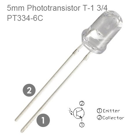
The figure above shows the part drawing and schematic of the PT334-6C phototransistor. The brightness of the light shining on it determines how much current it will allow to pass into its collector terminal, and out through its emitter terminal (the brighter the light more the current).
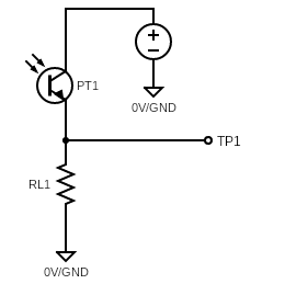
This phototransistor demands a suitable load resistor (bias resistor) to convert light/current into voltage. In the below shown schematic, the voltage at the output point TP1 of the ‘common-collector’ amplifier varies with light as the phototransistor PT1 lets more current flow when more light shines on it (or less current flow with less light).
That current also flows through the load resistor RL1. So, when more current passes through RL1, the voltage across it will be higher, and when less current passes, the voltage will be lower. Since one end of RL1 is tied to 0V/GND rail, the endpoint voltage at TP1 goes up with more current and falls down with less current. I hope you get it now!
From ON Semiconductor Application Note AN-3005, a phototransistor can be used in two modes, an active mode, and a switch mode.
In active mode, good for applications where it is desired to detect two levels of inputs for comparison, the phototransistor generates a response proportional to the light received by the component up to a certain light level. When the amount of light surpasses that level, the phototransistor becomes saturated and the output will not increase even as the light level increases.
Operating in the switch mode means that the phototransistor will either be off (cut-off) or on (saturated) in response to the light. This mode is useful when a digital output is required for object detection or encoder sensing.
By adjusting the load resistor in the circuit we can set the mode of operation. The correct value for the load resistor can be determined by the following equations:
- Active Mode: VCC > RL x ICC
- Switch Mode: VCC < RL x ICC
Where VCC is the supply voltage, RL is the load resistor value (common-collector or common-emitter configuration), and ICC is the maximum anticipated current.
Typically a resistor value of 5KΩ (or higher) is adequate to operate the phototransistor in the switch mode. The high-level output voltage in the switch mode should equal the supply voltage VCC, and the low-level output voltage should be less than 0.8V.
In active mode the output voltage is variable, rendering a value related to the amount of light. To use this mode, a reasonably low-value load resistor (<1KΩ) is required to prevent the output voltage from overstepping the supply voltage.
Well, let us now go to a practical experiment…
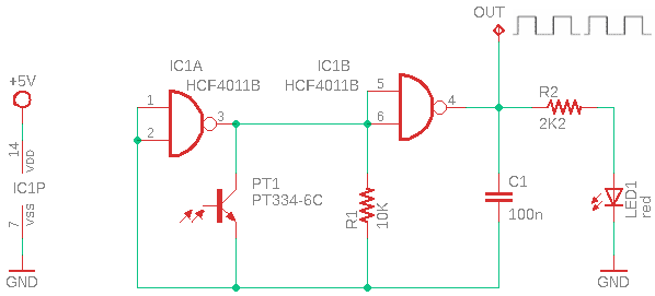
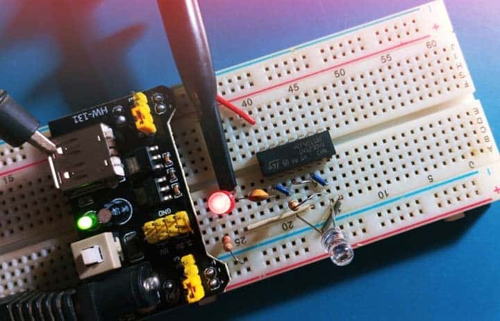
This experimental Light-Controlled Oscillator circuit uses the PT334-6C phototransistor as a light sensors. So, the changes in the resistance of the phototransistor, based on the light falling onto it, vary the oscillator frequency. The capacitor C1 and resistor R1 determine the central frequency of the square wave oscillator, and with the values given, it will be in the audible band (circa 250Hz to 1kHz) as I observed with an oscilloscope on my quick and dirty breadboard setup.
The HCF4011B is an ‘antique’ but still available QUAD 2 INPUT NAND GATE monolithic integrated circuit fabricated in Metal Oxide Discrete Semiconductors technology. All of its inputs and outputs are buffered.
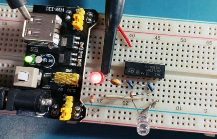
As you might noticed, I used ST’s HCF4011BE IC for the experiments. I was able to get satisfactory results from this setup. Some more experiments are planned, but I do not have much time for detailed documentation right now. OK, see you next time!