There is no doubt that nowadays we are seeing more logic-level MOSFETs being used in microcontroller-based hobby electronics circuits and projects.
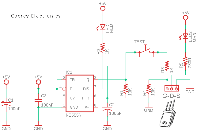
So this week’s little post is about building a quick go/no-go tester for the most widely used N-Channel Logic-Level MOSFETs. As you can see in the below schematic diagram, this is an inexpensive and easy-to-build MOSFET tester.
The circuit presented here is pretty simple and straightforward.
Basically, the tester connects the MOSFET to be tested as a solid state switch and injects a low-frequency square wave in the gate (G) through a momentary pushbutton switch (TEST) and checks that the corresponding green indicator (LED2) flashes. If the indicator remains on in a steady state it is indicative that there is a short circuit between the drain (D) and source (S) of the device under test.
Using only a single 555 timer Integrated Circuit (IC1), a low-frequency square wave is generated as IC1 operates as a nearly symmetrical square wave generator. The timing components of the square wave oscillator are the 10KΩ resistor (R1) and the 100uF capacitor (C2), so the resultant test frequency (output frequency) is close to 0.7Hz.
The power of the tester is supplied by a regulated 5VDC source while the red lamp (LED1) functions as an invariably flashing ‘tester ready’ indicator.
When a good working MOSFET is connected, the green LED2 will remain dark. Pressing the TEST button causes the green LED2 to flash. Illumination and flashing of the green LED2 indicate a test frequency of 0.7Hz.
If the green LED2 remains illuminated during this test, it indicates that the MOSFET under test is shorted, and if it remains dark (while LED1 is flashing), it indicates that the MOSFET under test may be open.
Also, if the MOSFET under test is shorted, the green LED2 lights up without pressing the TEST button, while flashing appears naturally on the red LED1.
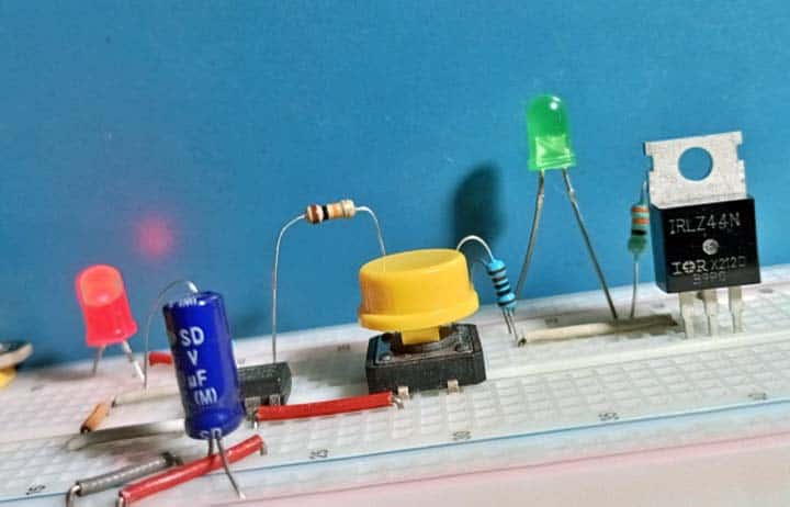
Here is a casual snap of my breadboard build of the MOSFET tester. As you can see, the MOSFET under test at this time is the popular IRLZ44N logic-level power MOSFET.
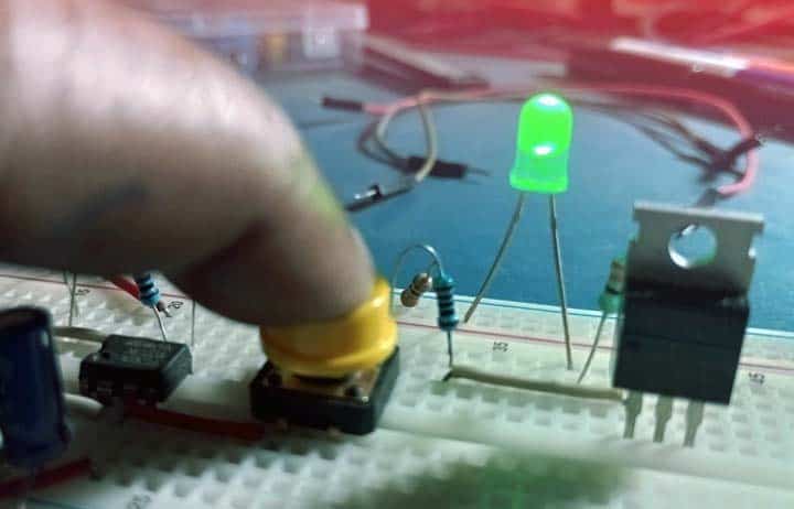
Also, here is a quick snap taken while testing some MOSFETs…
As an aside, there are two different types of MOSFETs with respect to Vgs (voltage from gate to source). A regular mosfet will require around 10V to ensure it is fully on. At 10V the Rds (on) will typically be at its minimum value for the entire voltage range. Note that the Rds(on) is simply the amount of resistance that the MOSFET has across its source to drain when fully turned on.
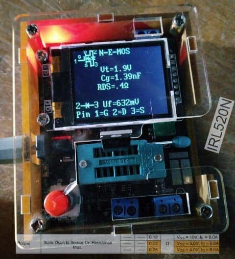
A logic-level MOSFET, on the other hand, only requires 5V or even less instead of the 10V norm to ensure it is fully on (see a sample test snap below). The key advantage of this is obvious – you can directly turn a logic-level MOSFET on or off from a TTL microcontroller.
So, that is it. I have plenty more to add to this design concept, so please consider it incomplete, as is the case with most of my posts, but it all takes time.
Just a spoiler, next in this series might be the construction project of a Universal BJT and MOSFET Tester with some automatic test features. Stay Tuned!