A zener diode is often used as a simple voltage reference device. This post looks at how to create a variable (or adjustable) zener diode.
Apparently, you can purchase the long-familiar programmable precision voltage reference chip TL431, but this is a fun little project. So how cool would it be if we could build our own variable zener diode from a few discrete components. OK, we can!
The figure below shows the most classical application of a regular zener diode as a voltage regulator.
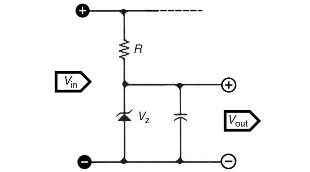
This type of a classic zener diode shunt regulator is commonly used for very local voltage regulation for less than 200mW of a load. As you can see, a series resistance is situated between the positive power supply rail and is used to limit the current to the zener diode and load.
Now see some rough design pointers to help you go with the zener diode shunt regulator concept shown above…
First, pick the zener diode based on the output voltage requirement (Vz = Vout).
Next decide the maximum output current (Iout_max). Note that the zener diode must be able to handle the totality of this current.
As with most voltage regulator circuits, the input voltage (Vin) must be slightly higher than the zener voltage (Vz) in order to keep the zener diode in reverse breakdown. Otherwise, the output voltage (Vout) will simply follow the input voltage (Vin).
The resistor (R) will shoulder the rest of the voltage drop not handled by the zener diode, which is the difference of the input voltage (Vin) and the output voltage (Vout).
It is easy to work out the resistor value (and its power rating) using Ohm’s Law, where the resistance is the voltage drop across the resistor divided by the maximum output current (Vin-Vout/Iout_max).
Since the zener diode itself demands some current to detain in reverse breakdown, typically in the order of 5mA, the resistor value may be lowered somewhat to accommodate.
Zener diodes also have power ratings. So to calculate the maximum power the zener diode will claim (the zener diode power dissipation), multiply the maximum output current by the zener voltage (Iout_max x Vz).
Here is a zener diode datasheet.
With me so far? Well, now let us move to the next session dealing with a variable zener diode design…
The below shown circuit is in fact a loosely adapted version of a well-worn design which boasts certain degree of flexibility with respect to a regular zener diode. The circuitry can be easily assembled on a small perfboard, and it is able to handle currents up to 100mA safely.
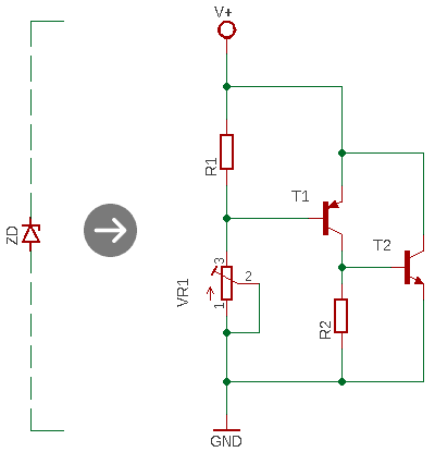
- R1: 1KΩ
- R2: 1KΩ
- VR1: 10KΩ Trimpot (multiturn trimpot recommended)
- T1: S8550
- T2: S8050
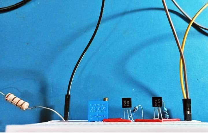
Here is a snap of my breadboard mock-up:

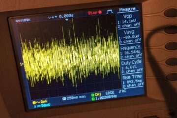
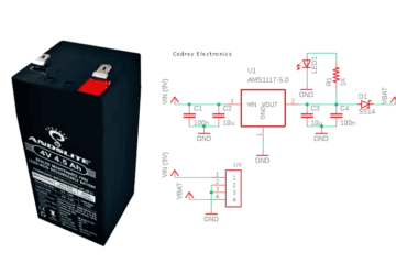
I have successfully tested this setup as a 2.7V (and 3.3V) zener diode powered from a 6V battery through a 100Ω/1W series resistor (see below).
In most cases making a variable zener diode is a reasonably easy task, and it can be a clever pick for little circuits that require only a few milliamperes of current. Its working is a bit tricky but elegant when you interpret it. Have Fun!