For today’s post, I thought it would be a good idea to see if I could create a reliable soft latching switch mechanism using a handful of electronic components lying around…
First of all, note that a latching toggle switch is one of the most popular mechanical switches, but here we are going to make its electronic version, that is, a soft latching toggle switch with a momentary push button. Well, let us get started…
We often want to turn a device on and off by pressing a push button. A soft latching (or soft latch) switch circuit allows a momentary push button switch to perform two tasks – turning the device on and turning the device off. A soft latch toggle switch also allows the button switch to be installed remotely via inexpensive low voltage cables.
Simply, we can resort to a circuit like the one shown in the figure below for that.

Using a single momentary pushbutton switch to alternately toggle a device on and off obviously demands a circuit containing a bistable logic latch. Such a latch can however be easily implemented by using positive feedback around any two inverting logic gates. As you can see in the above figure, the example presented here is a basic soft latching toggle switch circuit realized with the help of a commonly available CMOS IC – the HCF4011BE.
The HCF4011BE is a quad 2-input NAND gate monolithic IC with buffered inputs and outputs.
In this circuit, when the power (+5V) is first applied, the capacitor (C1) at the input of the first gate of the HCF4011B (IC1A) guarantees that the output (OUT) is initially latched low (L). This state is signalled instantly by the ‘optional’ visual indicator (LED1). Thereafter, the button (S1) presses toggle the output high and low (H/L).
This concept is in fact based on a very common textbook circuit widely used in electronics engineering courses in many areas. That is because at this simple level of electronics, there is no reinventing the wheel (someone has already come up with clever ideas somewhere).
Initially I replicated the classic textbook circuit exactly but ran into some trouble. While very simple, the textbook version is somewhat sensitive to the duration of the pushbutton press. That said, I have noticed a tendency for the circuit to vacillate if the momentary pushbutton switch is held down for a bit more period of time (at least in my case).
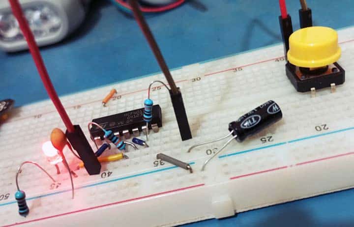
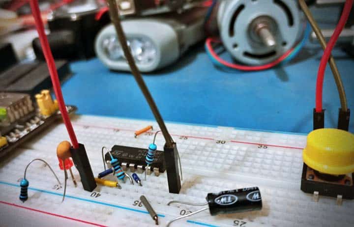
So, I did some design calculations and modified the circuitry by changing the values of the capacitors (as shown in my above schematic). Needless to say, my breadboard version (see below) worked perfectly as expected after that (do not hesitate to adapt and experiment).
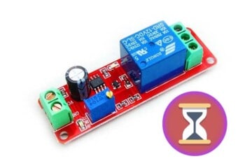
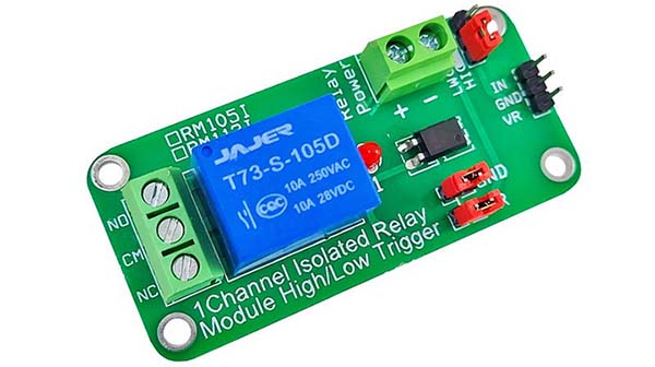
To turn on the soft latch switch circuit into a power driver, the output point of the circuit may be used to drive a cheap single-channel relay module with isolated high/low trigger input (see a sample below). This gives a lot of flexibility!
There are a few more advantages of using momentary switches. It can be a footswitch or whatever else you want. You can also toggle the soft latch circuitry from a number of switches allowing for multiple remote control points.
Finally, on a microcontroller you can easily program a pushbutton interface to perform both switch debouncing and implement a toggle switch function. But what is the fun in doing so, especially when you can build a simple yet brilliant standalone soft latch circuitry with few readily available cheap components?
And, if you are doing your own research, you will likely find countless design ideas which look similar but have a few differences, but most of the time those circuits are adaptable. I hope this little post is a good starting point. Have Fun!


