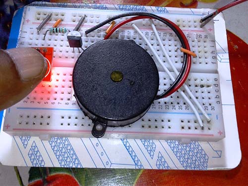
Every once in a while, I have found myself needing a quick circuit to blink a light emitting diode. It is quite easy to build simple microcontroller circuits which performs this task thru a few lines of code, however, this is an overkill and is not an approach I will be looking at here.
Therefore, the circuit idea I have shown here is realized with the help of a handful of inexpensive electronics components. This makes construction very easy and all you have to do is pick some silly parts from your junk box.
Well, let us see the schematic…
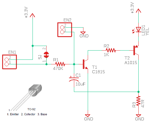
And, the list of components…
- T1: C1815
- T2: A1015
- LED1: 5mm Yellow LED
- C1: 10uF/16v
- R1: 470KΩ ¼ w
- R2: 1KΩ ¼ w
- R3: 47Ω ¼ w
This circuit flashes a regular LED and uses a 3V-3.3V DC supply. It has certain advantages over a flashing LED you can buy nowadays as an individual item. First of all you can use a red, green, amber, or yellow LED here to get something better than a single-color flashing LED. Besides, it pulses the LED with a higher peak current to give a brighter illumination and consumes relatively less average current, so seems better for lifetime battery operation.
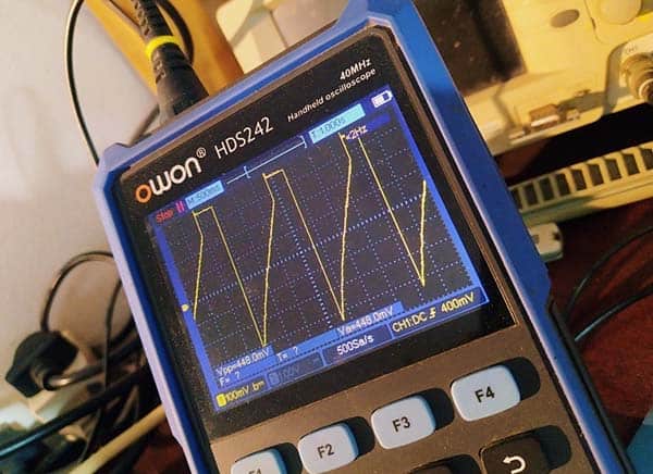
And this is what befalls in the circuit. Simply, it works on the basis of switching the transistor firstly by the very small amount of current delivered by the high-value resistor R1 and then from energy stored in the electrolytic capacitor C1. Note that the off-state is very long and the on-state is very short, and that is why the LED renders a brief flash. That is, the charge time of the capacitor is considerably longer than the discharge time as depicted in the below randomly taken oscillogram. The current through the LED is limited by the 47Ω resistor (R3).
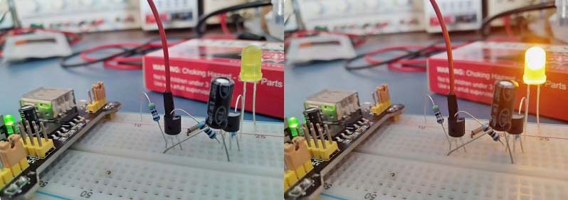
There is plenty of scope for tweaking this little circuit, i.e., by changing the values of R1, R3, and C1. Shown are the values I used in my breadboard prototype which worked fairly well. However, the flashing pattern is somewhat irregular though not readily apparent.
Also, you can use this circuit without much modifications to make something different like a crude wet or dry surface sensor. See a couple of related pointers in the table below.
| SOLDER JUMPER SJ | INPUT EN1 | INPUT EN2 | LED FLASHER |
| SHORT | DON’T CARE | SHORT/LOW Ω | OFF |
| OPEN | SHORT/LOW Ω | OPEN | ON |
Finally, I have to admit that this post is going to look frivolous. That is how it is…
But this is the outcome of an inspired experiment. And, I have always wanted to post whatever proved to be practicable for me at least once, in the hope that it might save some time to myself and others in the future. So, let us leave it open for now!

