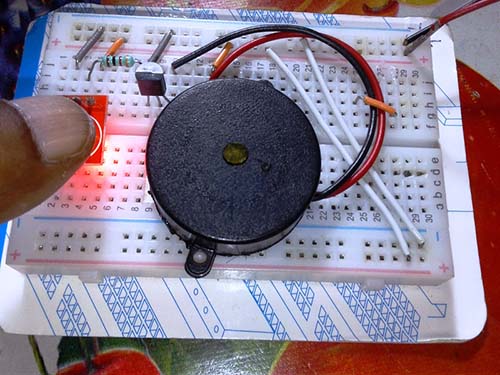
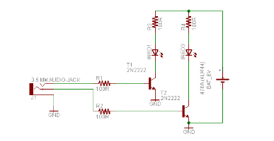
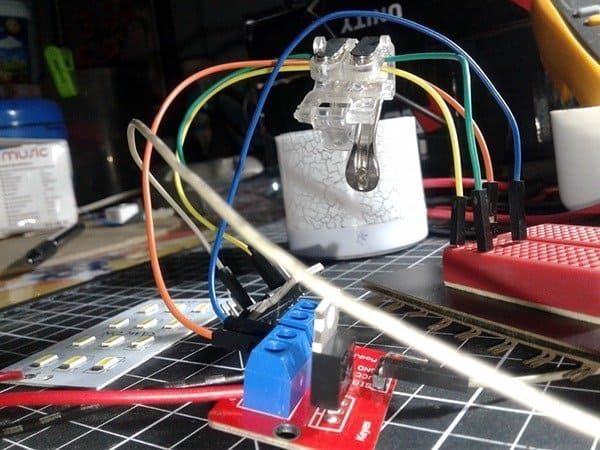
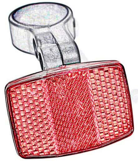
As we know, a reflector is a small, often red, reflective disc on the back of a vehicle that reflects the headlights of other vehicles.
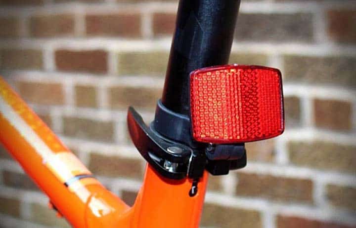
That is fine, but this little post is about constructing a cute e-reflector (active reflector) for bicycles. Since bike reflectors are highly recommended for all kinds of bicycles as means to improve visibility after dark, we hope our STEM kids and masters will find this do-it-yourself project interesting and useful.
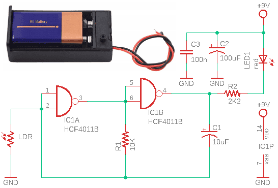
As can be seen in the schematic above, the most important part of this little design is the HCF4011B Quad 2-Input NAND Gate chip (IC1).
Next important component is the LDR (light-dependent resistor). This photoresistor has the useful property that its resistance depends on the amount of incident light (the more the light, the lower the resistance).
The IC1-LDR combination acts as a light-sensitive low-frequency oscillator.
In high ambient light conditions, the LDR remains in a low resistance state so the output of IC1 stays permanently low (L) and LED1 remains on without blinking (oscillator disabled).
However, a low ambient light condition causes the LDR resistance to increase and then the output voltage starts pulsing (oscillator enabled).
Subsequently, LED1 starts blinking. The LED used in this circuit was a 10mm high-intensity red LED (just a sample datasheet).
So, this e-reflector has a steady red light in a high light level condition, but when riding through a low light or dark area it renders a more trancing flashing red light.
For the power source, it is recommended (in view of safety and compactness) to use the pretty common 6F22 9V battery.
As an aside, enthusiastic experimenters can try tweaking the basic circuit by changing the values of R1 and C1 to alter the basic oscillator frequency as desired. In any case, enjoy your tinkering!
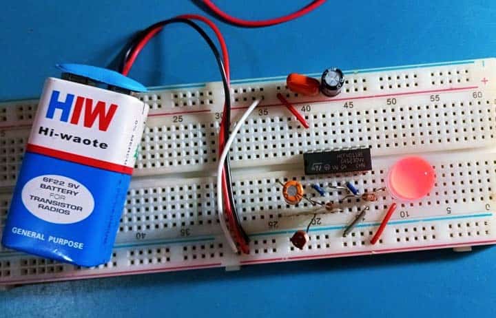
Everything always looks good on paper. So, I breadboarded the circuit just for a sanity check. And in the end, I was quite satisfied with the results.
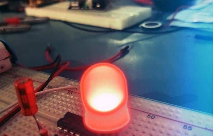
These are the recommended parts:
- IC1: HCF4011BE or CD4011B
- LED1: 10mm Red LED
- LDR: 5mm LDR (GL55xx Series)
- R1: 10KΩ ¼ W
- R2: 2.2KΩ ¼ W
- C1: 10uF/25V
- C2: 100uF/25V
- C3: 100nF
- BATTERY: 6F22 9V & 9V Battery Holder/Box with ON/OFF Switch (see below)
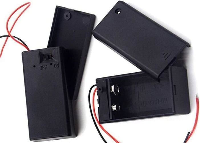
Needless to say, it would be nice to use a 3D-printed enclosure for your e-reflector, as such an outer shell will give it a luxurious touch.
An artistic rendering of a model e-reflector enclosure is shown below for your reference.
Finally, I hope you have been able to follow this fun project without any issues. If you do come across a problem, have feedback, I have missed something or anything else you would like to say, then feel free to drop a comment below. There is so much you can do with this cool little circuit. Let us leave it open for now!

