A current mirror is a circuit segment that functions to produce a copy of the current flowing into or out of an input terminal by replicating the current in an output terminal. In the analog electronics world, current mirror is one of the most used concepts, and it is commonly used to replicate current from one branch of the circuit to another. But a current mirror can also be used as a biasing network or as a pseudo current source. The goal of this post is to share a few things about bipolar junction transistor (BJT) current mirrors…

So, a current mirror copies a current through one active device by controlling the current in another active device. If the input current is constant, the replicated current is also constant. Note that a current mirror features a high output impedance to help keep the output current constant regardless of loading and low input impedance to keep the input current constant irrespective of the drive. A primary practical application of current mirrors is biasing amplifiers in integrated circuits.
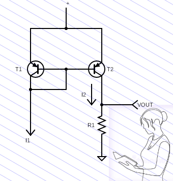
Let us look at the basic form of an PNP BJT current mirror. The typical setup shown next works well when the two BJTs are perfectly matched, that is to say, they have the same beta and will have the same Vbe drop (the better they are matched the more exact the current mirroring will be).
In this case, the input current (I1) causes a voltage across the base-emitter junction of T1. This voltage is also applied to the base-emitter junction of T2. This will cause a collector current (I2) in T2, which is almost equal to the input current (I1). Resistor R1 converts the collector current I2 to a voltage.
An essential thing here is that the transistors involved all have to match in key lineaments (including how they respond to things like temperature or voltage shifts). You can definitely find discrete transistors that have multiple devices built on a single substrate, but nowadays dual transistors are pretty expensive and are not very common. Below you can see a classical Dual PNP Transistor – the 2SA979 from Mitsubishi. Motorola’s 2N3806 is another great vintage electronics example.
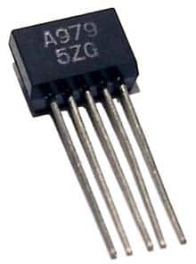
It should be noted that the current mirror operation can be susceptible to drifts in the bias voltage, changes in temperature, as well as transistor matching, layout considerations, and other factors. However, when using matched transistors in a BJT current mirror, the input current to output current ratio (gain) is one, and the currents are equal.
And now, of course, we need to build something to quench our thirst…
Well, get ready to make a tricky high-side current mirror with the two discrete PNP transistors as shown in the below schematic (Do your homework for an NPN version).
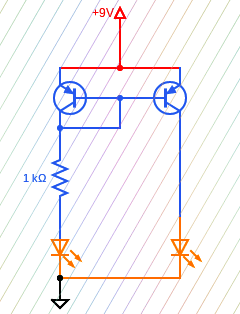
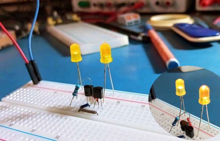
Here, the current through the first LED is set by the 1KΩ resistor. The second LED does not need a resistor because the mirrored current is the same, so both LEDs will have almost equal brightness.
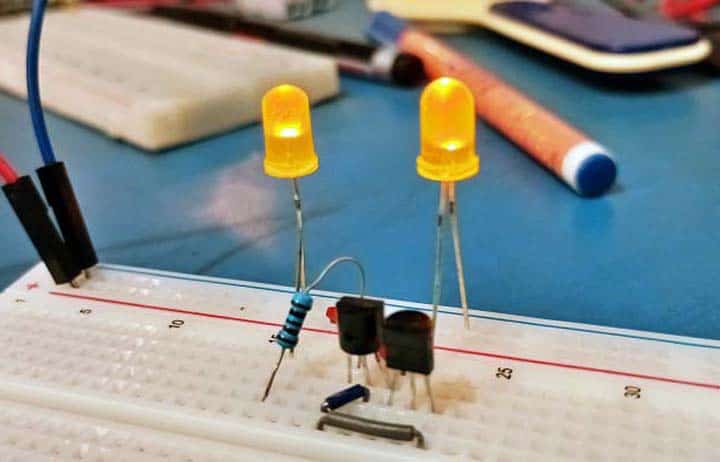
It may sound unbelievable to many kids today, but I still have a limited stock of used 2N3806 dual PNP transistors as I can find them in my rusty junk boxes from the 1980s.
But I built my recent experimental prototype on a breadboard with two 2SA1015GR transistors, because I am sure most of you here would not dare pay DigiKey or similar high-profile sellers an exorbitant amount of money for a single 2N3806 transistor!
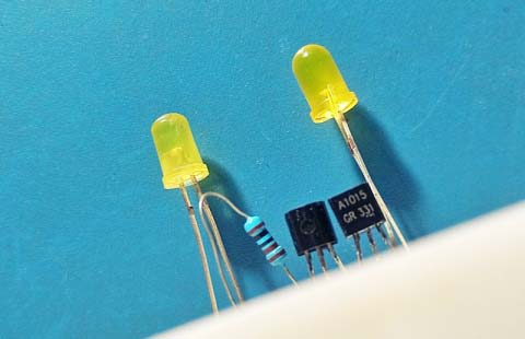
Current mirrors are well known circuits in electronics but are mostly obscure except to serious analog electronics designers. In the next part of this series we will look at respective common current mirror topologies and where they are used. So stay tuned…
What is much less known?
- Wilson Current Mirror
- Widlar Current Mirror
- Mirror Gain other than unity
