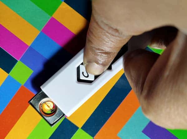
I was after a cheap windproof electric lighter to use in and around the home. Well, they are cheap enough to buy heaps of them, so I bought a pair of USB cigarette lighters to light candles and incense sticks. Yay! No more burnt fingers using risky flame lighters!
So, what is inside the cheapo electronic fire starter?
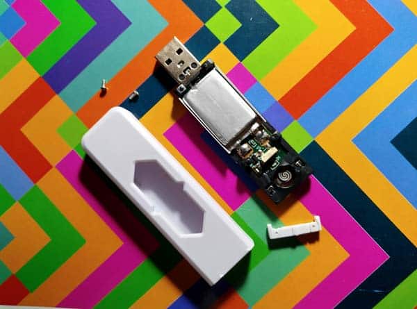
I decided to open up one of my USB cigarette lighters to see what makes these flameless lighters work.
First off, I was pleasantly surprised to see a flat 1S (3.7V) LiPo battery pack, however without anything printed on it – perhaps a 280mAh rated one but I’m not sure.
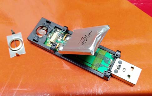
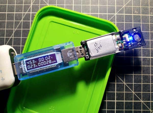
So, I plugged its retractable USB male connector into a “weak” USB power bank to roughly measure the charging current. As you can see it was around 230mA at 4.5V as indicated by my USB power monitor (https://www.electroschematics.com/usb-power-monitor-review-teardown/).
Below is a basic system diagram of the USB cigarette lighter, prepared by me just to explain something about its internal electronics.
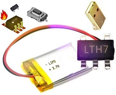
The circuit board holds a few chip components (SMDs). The inbuilt USB charger is based on the LTC4054 (SMD code: LTH7) battery charger IC (https://www.codrey.com/electronic-circuits/solar-usb-li-ion-battery-charger/).
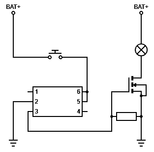
Rest of the circuit resembles the heater controller design of an e-cigarette very much (https://en.wikipedia.org/wiki/Electronic_cigarette). Below is the heater controller’s schematic, again a rough diagram prepared by me.
And now let’s check the heater (heating wire) control electronics!
As you can see in the above schematic, positive terminal of the LiPo battery (BAT+) is routed to the MOSFET (SMD code: 2300) through the heater coil. The heating wire is made out of thin metal compounds specifically designed to handle rapid temperature rising.
The MOSFET (https://www.vishay.com/docs/65701/si2300ds.pdf) is configured as a low-side switch which is controlled by the 6-pin IC (SMD code: _6243) via the pushbutton switch. Note that one heating cycle of this USB cigarette lighter will cut-off after ten seconds of use to prevent overheating. This auto-off feature also preserves battery life.
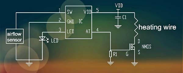
Sadly, there is no way to identify the 6-pin chip yet! However, it appears like a “single-channel single-pole double-throw analog switch” similar to the SN74LVC1G3157 IC (https://www.ti.com/lit/ds/symlink/sn74lvc1g3157.pdf), or a loosely-cloned version of an “e-cigarette heater controller” like the XM7100 IC (https://datasheetspdf.com/pdf-file/904984/ETC/XM7100/1).
TX818C is another widely known e-cigarette driver ASIC (http://www.txsemi.com/pdf/%E5%AE%9A%E5%88%B6IC/%E7%94%B5%E5%AD%90%E7%83%9F/TX818C_V1.0.pdf).
If you want to know more about e-cigarette electronics, further reading is only a mouse-click away! https://patents.google.com/patent/US20130319989A1/en
Start Hacking!
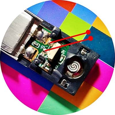
For one of my projects, I need a small heating coil. There are a lot of cheap USB cigarette lighters available which made me give interfacing my circuitry with one a shot. After probing around on the circuit board for a while I did find a solution that could be used for employing the entire lighter as a “remote-controlled heating wire” in my project. The solution is extremely simple as can be seen in the below figure – just desolder the button switch, and extend two magnet wires (https://en.wikipedia.org/wiki/Magnet_wire) from the solder pads. Simple, yeh?
This would almost work by itself except you will need an external electronic switch circuit to mimic the button switch on the cigarette lighter. There are many ways to do this, for instance, you can (hopefully) see a fairly straightforward idea in my “remote-controlled fire cracker” project scheduled to be posted here after some weeks. What if your fireworks are controlled by a wireless remote? Maybe you will become lazy. But it seems marvelous, isn’t it?
The other thing to do would be to play with a Chinese “arc ignition lighter” kit to learn about its internal electronics secrets. Further updates will follow!
