Circuit of a little solid-state heater controller is described here. This circuit can be used to regulate standard resistive heating coils widely used in AC230V grid supply powered heating gadgets like Air Heaters, Hot Air Blowers, etc.
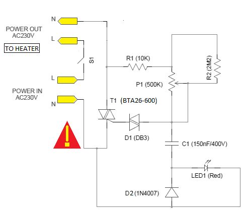
The solid-state heater controller circuit built around the inexpensive BTA26-600 (T1) triac. Phase control is one of the most commonly used firing methods with a triac, and here a basic idea is developed for the purpose. The RC time constants (R1/R2-P1-C1) provide a phase shifted ac signal to the diac – DB3 (D1).When the voltage on C1 exceeds the break over voltage of D1, it breaks down and triggers the triac T1. The 500K Potentiometer (P1) will provide a smooth continuous control of power to the output load, i.e. heating element of the device under control. The 5mm Red LED (LED1) is a power condition indicator, and S1 is the power on/off switch. Even if the power dissipation of the triac (T1) is not high, a small heat sink must be provided. The heat sink should not be allowed to come in direct contact with any external metallic/conductive objects.
After construction and testing, the entire assembly should be enclosed in a suitable plastic/wooden box. Finally, note that a insulated shaft potentiometer is crucial as P1.
CAUTION! THE CIRCUIT CONTAINS DANGEROUS, HIGH VOLTAGE POTENTIALS


