This article describes a basic idea that can be used to build your own simple video security systems such as a door video security camera. In these times you can buy astonishingly cheap Car Rear-View systems from Chinese & Indian online stores. The idea presented here is based on such a product, so buy one for yourself from your trusted online seller.
Hardware Overview
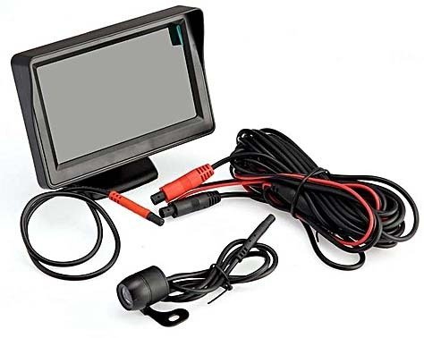
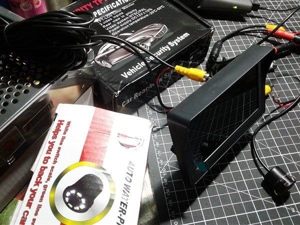
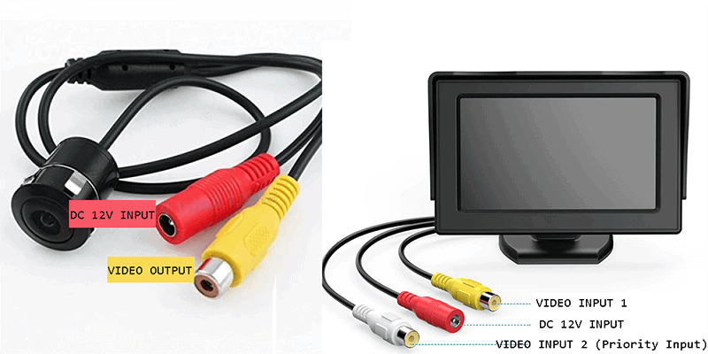
Usually the kit comprises a 4.3″ TFT car monitor and a minuscule night vision car rear-view camera bundled with mounting accessories and power/signal cables. Since the rear-view system is designed to run on a 12V automobile battery, you should also buy a separate smps adapter that can deliver at least 1A of output current at 12V.
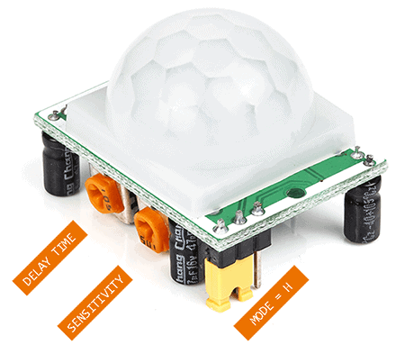
Next in line is a bunch of easily available electronics components, and the key part is a very common passive infrared (PIR) motion detector module HC-SR501. The PIR sensor hardly needs any explanation (read relevant articles published here) but you can see an annotated figure below.
Controller Circuit
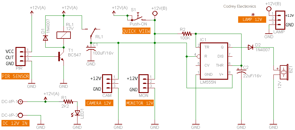
Here’s the schematic of the required security system controller. It’s merely a motion-sensor relay driver combined with an audio annunciator, lucid enough to perceive and quite easy to construct.
Operation of the controller circuit is extremely simple. Normally the system is in idle state so that the inputted dc supply (12V-A) is not available to the video camera and monitor. The audio annunciator built around the 555 timer (IC1) remains inactive as it lacks the dc supply, too.
Whenever the motion detector (PIR SENSOR) notes that there’s a human motion, it will activate the electromagnetic relay (RL1) for a finite time (decided by its delay trimpot setting) through the BC547 driver transistor (T1) thus rest of the system gets dc supply (12V-B) through the relay contacts. Consequently, the video camera output is available on the monitor screen, and a short beep (only once) is generated by the piezo-sounder (BZ1) as a warning signal. Finally the entire system returns to its idle state just after the pre-fixed duration.
Note that you can increase/decrease the timeout period using the ‘delay’ adjust trimpot in HC-SR501, and the detection range through ‘sensitivity’ adjust trimpot. For this project, keep PIR motion sensor’s mode switch in ‘H’ position as in that repeatable (H) mode the sensor will go active when a motion is detected within its range and revert to initial state after the particular time. The ‘quick view’ switch (S1) is included intentionally to override the motion sensor so that you can see the video at anytime when you push and hold it. There’s also one switched 12V output for running a 12V dc exterior lamp, anyway, it’s not very necessary because of the night vision supported rear-view camera.
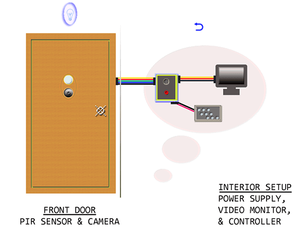
Well, take a look at the security system overview (just an installation pointer, that’s all).
Points to remember
- Video Output (yellow) of the rear-view camera should be connected to Video Input 1 or 2 (yellow or white) of the TFT monitor without any intervention
- Power wires (red and black) of the rear-view camera and the TFT monitor should be wired to their respective terminals in the controller circuit, with correct +/-polarity. Video Input 2 is the ‘priority input’ tailored especially for automobile use
- Usually the TFT monitor displays flipped video content with/without multi-colored guidelines/markers laid over. It’s actually done internally by the rear-view camera, hence there’s no easy way for refinements. Not a big concern here, never mind
The observed total current requirement of the entire setup is well below 250mA @ 12V (without the exterior lamp). Anyway I still prefer one 12V/1A smps adapter
This project got its genesis when I needed a simple, yet reliable door video security camera for a private purpose, built around off-the-rack parts. However, the idea is versatile enough that it should be able to find room for some other practical application!

