As you know, a mercury switch can be used to detect any inclination with respect to gravity. For example, suppose your home security alarm wants to know when someone opens the lid of your cash box, the mercury tilt switch will send an alert to the alarm system when the lid reaches a certain angle. Another potential application is its use in certain toys and robots.
This is the link to a related post published before a couple of years: Magic Cup Light Module
See also: Universal Tilt Sensor
Recently I bought a bunch of the good old mercury tilt switches for a funny seesaw project (you know, seesaw is plaything consisting of a board balanced on a fulcrum). So, this post shares some things about that 3mm mercury tilt switch, hopefully it will be helpful for many students and novices.
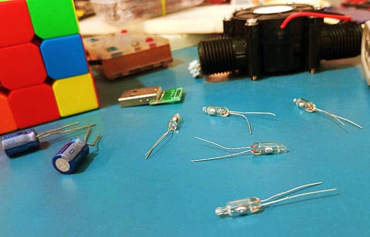
Before getting into the practical notes, let us look at some significant things about common mercury tilt switches.
Notice that first,the mercury in a mercury tilt switch is encased in glass, with the connection leads going inside the encasing (typically inside there is either air, an inert gas, or a vacuum).
Next, as a safety note, Mercury (Hg) is poisonous!
It can be inhaled and absorbed through the skin and mucous membrane. Acute exposure to mercury vapor has been shown to result in profound central nervous system effects, including psychotic reactions characterized by delirium, hallucinations, and suicidal tendency (https://en.wikipedia.org/wiki/Mercury_(element)#Toxicity_and_safety).

Also note that an important feature of a mercury tilt switch compared to an accelerometer is that it can handle moderately high currents. So, if you want, you can have it control a lampor some other mighty device directly.
Well, let us go back to the main topic of the post, you can wire up a mercury tilt switch like any other switch, for example, as in the diagram below. Here, when the mercury tilt switch is tilted, it gives a logic-low (L) or logic-high (H) state output depending on its position.
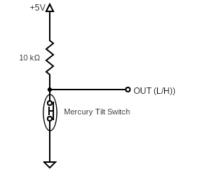
But, like most other mechanical switches, mercury switches have a problem called switch bounce. That is, when a switch is toggled, contacts have to physically travel from one point to another. As the components of the switch settle into their new position, they mechanically bounce, causing the underlying circuit to be opened and closed several times (Switch Debouncer – Hardware Guide).
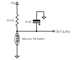
An easy electrical solution to the mercury tilt switch’s inherent bouncing problem is to put a capacitor between the output and ground (see below). If so, depending on the value of the capacitor, you can vary the time it takes to respond. Note that higher values will reduce the chance of a false trigger, but also reduce the response speed.
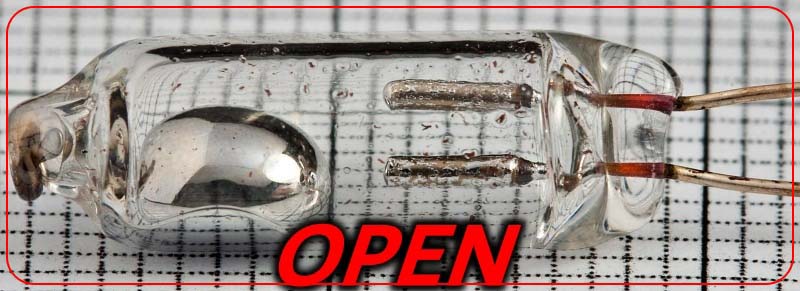
As noticed, switch contacts of my “hermetically sealed 3mm unidirectional mercury tip-over switch” are closed when vertical and open when tilted in any direction. According to the Amazon seller’s short description, it can handle a maximum dc voltage of 20V and a maximum current of 300mA (who knows).
So, with the help of a cheap mercury tilt switch you can make a lid monitoring sensor to detect when a cashbox or toolbox is being opened or tampered with, among other things, which can be used in conjunction with a microcontroller based security system.
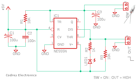
To get going with similar design ideas, here is a simple but useful mercury tilt switch module circuit that you can build yourself. This amended design (see below) allows you to connect any standard mercury tilt switch to any microcontroller and then ensure trouble-free operation at all times.
A small perfboard can hold nearly all components. After everything has been decently soldered together, you can fit everything into a prototype enclosure. And, the finished system can be installed on any surface using a piece of double-sided tape (the tape has pressure-sensitive adhesive exposed on both sides, allowing two parts to be bonded together by the tape between them).
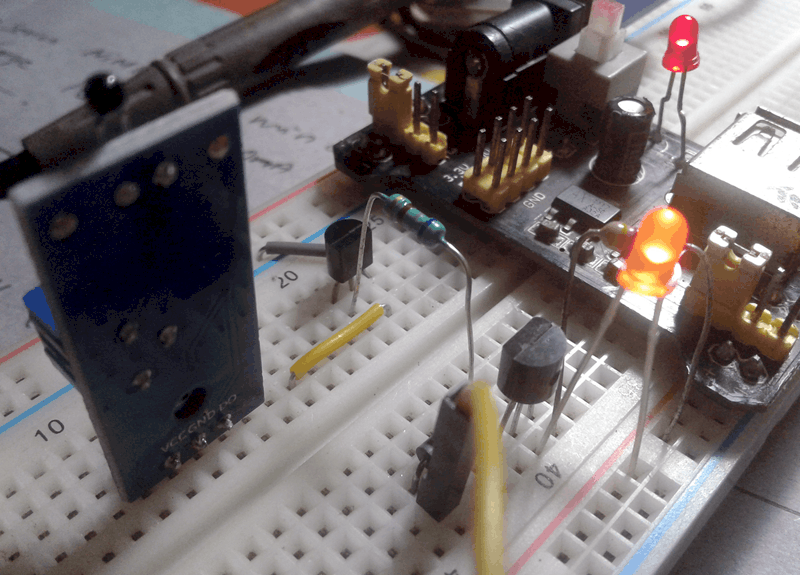
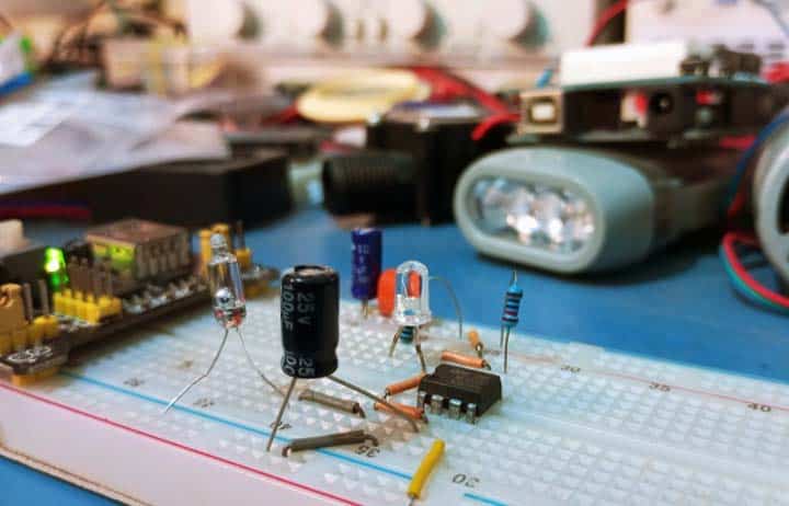
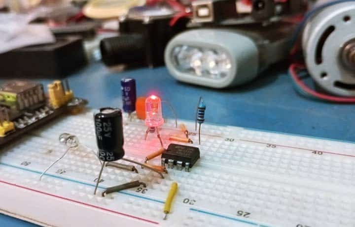
Below is a casual snap of my breadboard prototype. Note that the visual indicator LED1 will be off when the mercury tilt switch is in its “on” position, and the other way around.
Note at this point that Pin 7 of the 555 is an open-collector terminal. It can sink current (a pull-up resistor is needed), and its transistor is turned on by the same flip-flop that controls the actual output at Pin 3 which can sink or source current (Pin 7 has the same logic state as pin 3).
I will get to the aforementioned seesaw project later. In the interim, I plan to publish the design details of a fall alert device (medical alert system) that has a dedicated triaxial accelerometer at its core to measure speed, distance, and direction.
As always, I will be happy to share my ideas with you and I would love to hear yours. Cheers!

