Electronic Magnet Evaluator is a simple device incredibly useful for experimenters and students. With this little gadget one can not only detect the presence of a permanent magnet but also find out its south (S) and north (N) poles. Circuit of this portable device is designed for 9V battery operation.
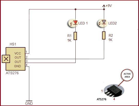
The circuit given below uses an inexpensive and commonly available integrated Hall sensor ATS276 (from Diodes Inc.) as the magnet sensor, sensitive enough to detect magnetic proximity at a distance of a few millimeters from the active area (marking side) of the sensor chip. In principle, the ATS276 chip internally includes the voltage regulator, protection diode, Hall plate, amplifier, comparator, and a pair of complementary open-collector outputs (DO, DOB). While the magnetic flux density (B) is larger than operate point (Bop), DO will turn on (low), and meanwhile DOB will turn off (high). Each output is latched until the magnetic flux (B) is lower than release point (Brp), and then DO,DOB transfer each state (see its datasheet to learn more).
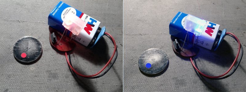
The entire circuit can be fabricated on a little piece of veroboard. While mounting the Hall sensor (HS1), ensure that its active area (marking side) faces towards outside. Bringing the South pole of a permanent magnet to the close proximity of the Hall sensor will light up the blue LED (LED2), and bringing the North pole toggles the circuit to light up the red LED (LED1).
At most hardware stores, you can buy assorted permanent magnets at reasonable prices. The most common method for marking a permanent magnet is to color the North Pole Red and the South Pole Blue. Therefore, if the magnet has colors on it, the pole finding task is made infinitely easier. Else, you can use this funny device to get it right. That’s all!
& Here is the first version of my prototype, without its homemade enclosure:

