Here is one interesting circuit of an automatic, passive infrared motion sensor controlled, speed regulator switch for ceiling fans. The circuit, designed for AC230V operation is realized using generally available discrete components, and optimized for generic ceiling fans without any strange electronics on the inside.
Working of the circuit is very simple and self-explanatory. When the connected ceiling fan is powered up, the fan starts working at a very slow speed. However, if a valid human movement is detected by the passive infrared motion sensor, the circuit wakes up from its standby mode, and switches the fan to its maximum speed for a finite duration. In the presented design, you can see options to set the rate of the slow speed, and the duration of the full speed by altering/adjusting some component values/settings. Okay, first of all have a look at the schematic:

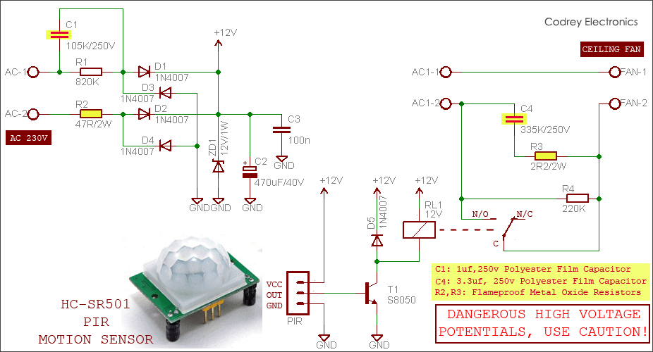
As you can see, here a transformer-less power supply is used to convert the AC230V input to DC12V output. A 12V electromagnetic relay (RL1) is included to bypass the “tricky” capacitive-fan speed regulator (C4-R3-R4) when the circuit is in active state. This relay is controlled by an HC-SR501 passive infrared (PIR) motion sensor module with the help of a general-purpose NPN switching transistor S8050 (T1).

Tuning up..
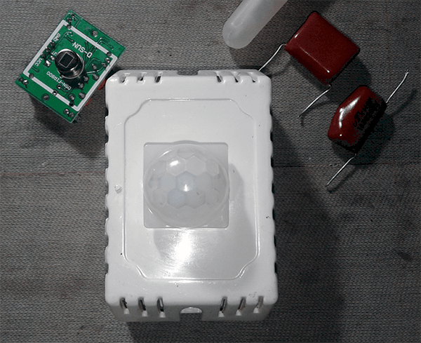
The main role of components C4-R3-R4 is to limit the voltage across the ceiling fan. Here, R3 is used in series with the capacitor C4 in order to limit the current flowing to the capacitor to a safe value. The parallel resistor R4 serves as a discharging path for the capacitor for each supply cycle. The voltage across the capacitor is given by the formula V = Q/C where Q is the charge across the capacitor and C is the capacitance. According to the formula, by increasing the value of the capacitor, speed of the fan can be increased. Thus, by employing a suitable capacitor fan’s speed (in standby mode) can be regulated. For example, try a 225K/250V capacitor as C4 to reduce the speed further, or try a 475K/250V capacitor to increase the speed. Since capacitor is the vital element here, in order to ensure reliable operation all the electrical parameters of the capacitor must be selected carefully. Although metallised polyester and metallised polypropylene capacitors fulfil the requirements of our application, metallised polyester capacitor scores over the later because of its comparatively high dielectric constant.
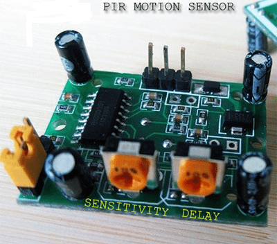
In the HC-SR501, there is a trimpot to control the ‘ON’ delay time (5s-18 minute) for the sensor. Turning the trimpot clockwise will give longer ‘ON’ delay time while turning anticlockwise will reduce the ‘ON’ delay time. Also there is another trimpot for the user to adjust detection sensitivity (the sensor offers sensitivity/distance range of approximately 3-7 meters). Take note, the PIR sensor requires a ‘warmup’ time in order to function properly. This is due to the settling time involved in ‘learning’ its environment (this could be anywhere from 10-60 seconds). During this time there should be as little motion as possible in the sensor’s field of view!


Very useful ckt
I want to know the overall power saving in using this cencor based ceiling fan switching with normal button operated, keeping in mind the buttons are often forgotten to be closed
Danish Khan: All the benefits of motion sensor switching narrow down to energy efficiency. The circuit given here consumes only very little current.
As I read, according to some recent studies by reputable agencies, motion sensors (occupancy sensors) can increase energy savings by up to 40-60%.
Coming to your inquiry, you can do the math based on the occupancy frequency and power consumption of your equipment.
Simply, it depends on the power rating of your ceiling fan which I do not know!