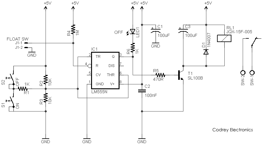
Here is the circuit diagram of an independent water pump switch controller with ‘soft’ on/off buttons. Since the circuit uses low-voltage switches, even a kid can operate it safely. Besides, there’s also a dry-run protection option to disable the water pump controller if the water level at the sump/underground storage tank goes below a certain level. This safeguards the water pump from costly damages. The circuit is built around the revered eight-legged timer chip – LM555, and a standard ‘eBay’ float switch is added for (optional) dry-run detection.
Main Circuit Diagram
Power Supply & Float Switch Selection
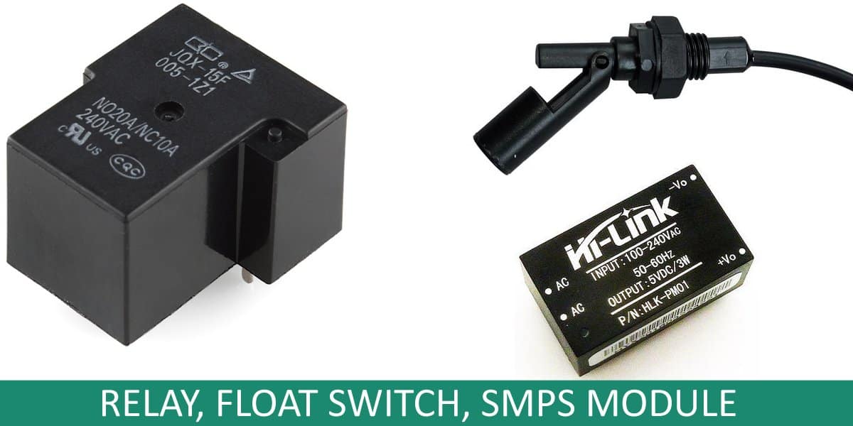
As you might noticed, a ‘beefy’ relay is used here to switch the water pump motor. The “JQX-15F-005” is a miniature heavy duty DC electromagnetic relay with a rated load of 20A/240V AC. Since operating current of the relay is very near to 200mA (@5V) you need a healthy smps power supply for this circuit. The low-profile type “HLK-PM01” smps module (from Hi-Link) will be a good choice here as it’s not only very efficient but also clean and safe.
Deciding whether your float switch needs to be normally open or normally closed for this circuit can be a little confusing. So I would like to clear things up. When it says the float switch is at rest, it mean that the float is not suspended in water. Here we want the switch to be off, when the float is at rest (and on when the sump/tank is empty), so we will need the switch to be normally opened. The “mini float switch” is a normally-opened (N/O) type float level switch. Install the switch in the sump/underground tank so that the switch remains in the ‘open-state’ until the water level falls below a certain mark. Surprisingly, the more convenient two-way (N/C & N/O) type float switches are also available from most online vendors right now.

