Having spent a few days messing on with building simple inductive proximity sensor circuits, I’m putting together anew inductive proximity detector device for a small-scale industry. I already have an expandable idea with the sensor type SN04-N but think I’m struggling from the fact it’s again based on a timeworn inductive proximity sensor, so I planned to have another go with a different type of compact proximity sensor. I’ve searched to find a simple but suitable sensor for a while and stumbled across the great site from a Chinese seller which offers a broad range discounts for the NJK-5002C Hall-Effect Sensor Proximity Switches.
One thing that really caught my attention was the new proximity sensor implements the Hall-Effect method of magnetic proximity detection rather than employing the conventional inductive technique for metal proximity detection!
Admittedly, it wasn’t totally clear to me quite how to make it ready for real-world practical applications by putting it together with some common components I had lying around. So this is by way of documenting how I got it working based on the info snips I gathered from respective websites. Anyway, before leaping into that story, let me say a few words about the most common inductive type proximity sensors as I think it might refresh your basic knowledge on such widely used detection devices. Well, let’s start!
Inductive Proximity Sensors
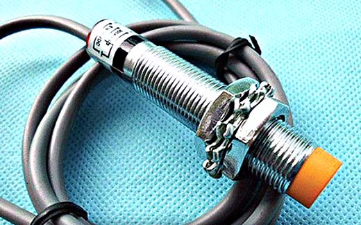
Inductive proximity sensors are broadly used to detect near by metal objects. In principle such sensors use currents induced by magnetic fields for the detection process, that means their working principle is based on a coil and oscillator that creates an electromagnetic field in the close surroundings of the sensor face. The presence of a metallic object (target) in its close proximity causes a dampening of the oscillation amplitude. The rise (or fall) of such oscillation is identified by a threshold circuit that changes the output of the sensor. The operating distance (proximity range) depends on the target’s shape and size and is strictly linked to the nature of the material. Note that Iron (Fe37) is a good target for inductive proximity sensors as it has “1 x Sn” sensitivity when compared with other metal objects. Usually, the operating distance (Sn) is denoted as the maximum distance (± 10%) from the proximity sensor to a square piece of Iron (Fe 37), 1mm thick with side’s equal to the diameter of the sensing face, that will initiate a change in the output of the proximity sensor.
That’s it! If you’re a voracious reader, you may be interested in reading this blog post about inductive proximity sensors https://automation-insights.blog/2014/03/05/basic-operating-principle-of-an-inductive-proximity-sensor/.
Also take a look at this DIY RPM Counter project based on the inductive proximity sensor SN04-N https://www.codrey.com/arduino-projects/arduino-tachometer/
Magnetic Proximity Sensors
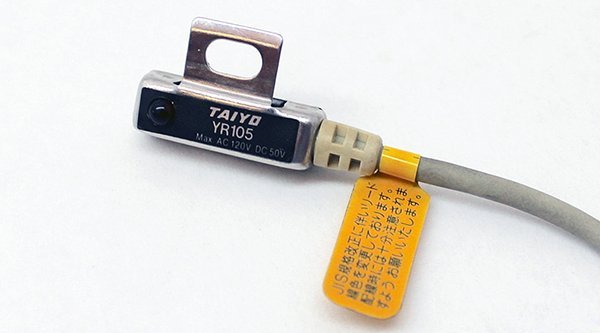
The simplest magnetic proximity sensor is based on the familiar ‘Reed Switch’, and such “magnetic reed switch proximity sensors” can be used easily to detect the presence of a magnetic object in its close proximity. Usually, like the aforesaid inductive proximity sensor, it can be used in RPM Counters, Limit/End Stop Detectors, and so forth. Nevertheless, a magnetic reed switch proximity sensor is effective only for detection of magnets, not common metal objects.
Here’s a DIY project grounded on the same ‘reed switch magnetic proximity detection’ principle https://www.codrey.com/arduino-projects/digital-pulse-counter/
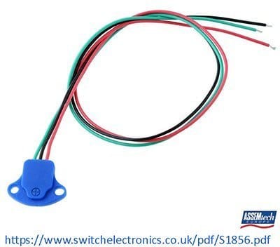
Next one in this series is the ‘Hall-Effect Sensor’ based proximity switch. Again, the “Hall-Effect Sensor Proximity Switch” works only with magnetic objects, and it’s much a ‘unipolar’ type. That means a Reed Switch will respond to any pole (south or north) of a magnet, but a Hall-Effect Sensor usually responds to one certain pole (usually south pole) of a magnet at a time. However the latter is more compact, fast, and has got a comparatively long lifespan.
- Unipolar Hall-Effect Sensor Basics: https://www.allegromicro.com/en/Insights-and-Innovations/Technical-Documents/Hall-Effect-Sensor-IC-Publications/Unipolar-Hall-Effect-Sensor-IC-Basics
- Unipolar Hall-Effect Sensor DIY Project: https://www.codrey.com/electronic-circuits/expansible-door-sensor/
NJK-5002C Hall-Effect Sensor Proximity Switch
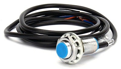
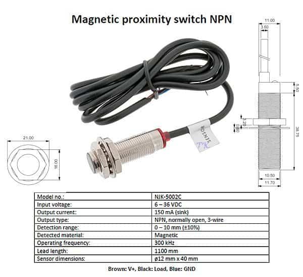
The NJK-5002C Hall-Effect Sensor Proximity Switch is in fact a simple magnetic proximity sensor with one ‘unipolar’ Hall-Effect Sensor chip at its core. Following is its quick features and specifications as supplied by my Chinese vendor.
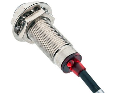
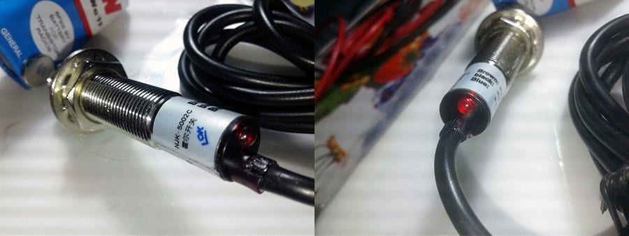
This 3-wire magnetic proximity sensor can be powered from any 6-36V DC power supply (12V typical), and its output – a normally open (N/O) NPN transistor’s collector lead – can drive any resistive/inductive DC load if its operating current is not more than 150mA maximum. The NJK-5002C is configured to work with the south pole (S) of a permanent magnet, located with in 10mm of its vicinity. There’s also one red LED indicator mounted at the rear of the sensor to announce the ‘on’ state (active state) of the device.
Practical Circuits
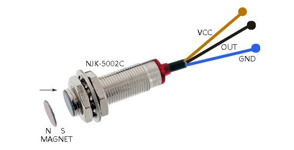
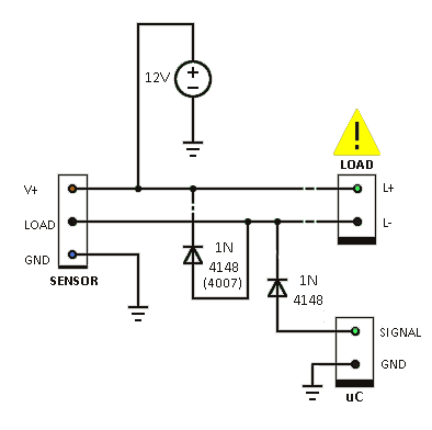
As mentioned (and as you can see) NJK-5002C is a 3-wire sensor. The brown wire is V+ lead (dc positive), blue wire is the Gnd (0v) lead, and the blue wire is the LOAD (current sink) lead.
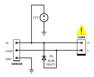
Here’s the basic wiring diagram for practical applications of the NJK-5002C sensor.
If your NJK-5002C can source 150mA of current, it’s safe to connect a standard electromagnetic relay, solid state relay module, dc buzzer, or a small hooter between its black and brown leads as pointed in the above schematic. Even so, I don’t take heed to the ‘6-36VDC input’ outrageous flaunt as I still like better to use 12VDC input for my NJK-5002C projects. Likewise I’d like to use the sensor for driving loads up to 50mA only (not 150mA) as I found that the sensors sold by most Chinese vendors are merely cheap knockoffs, and they can sink only 50mA of load current at 12VDC!
Next is to find a right answer to the question – how can I read the sensor output through a microcontroller? The main point to notice is that the ‘load’ output switches from 12V to 0V when powered by 12VDC. If routed directly to the input of the microcontroller it would exceed the I/O voltage rating of the microcontroller. To ‘cook’ the output to a 5V to 0V transition suitable for the microcontroller input, you could use a small signal diode (1N4148 for instance) between the output lead and your microcontroller, with its anode terminal at the microcontroller input. Then enable the internal pull-up of the concerned I/O port or add an external pull-up resistor (~10K), and there you go!
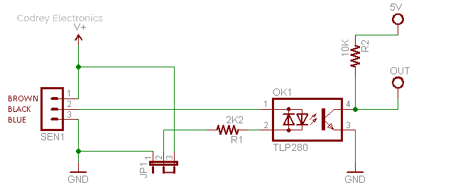
Following is the circuit of an isolated interface for microcontrollers. Since the design is centered on one ‘AC optocoupler’, it’s easy for you to invert or non-invert the final output of the proximity sensor. The 2-way jumper header (JP1) lets you do the mode selection at ease.
The Toshiba’s TLP280 surface-mount optocoupler consist of photo transistor, optically coupled to two gallium arsenide infrared emitting diodes connected inverse parallel. Note that Chinese knockoff of TLP280 usually comes with a foxing part number GB118-P280. One possible drop-in replacement part, as far as I know, is the PC814 optocoupler from Sharp.
Side Note
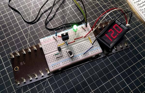
So after all I got it working in the easiest and most logical way I can, by using a few cheapest components lying around. I verified all setups and all them worked reasonably fine. However, don’t just go as this article says! First you have to verify which type of proximity sensor you’ve got. Use your brain!
Now I’m continuing my experiments with NJK-5002C, and as usual you can see a fully fledged do it yourself project using the same sensor in near future. Keep making amazing stuff. Good Luck!

can i use this switch to make up an ignition system to use on an old single cylinder engine ? and if so please advise me as to what i need,and a diagram of project,based on a 12VDC power sauce and 12 volt car coil.
Thanks John M Savy.
John M Savy: I’m sorry, I ‘ve very limited knowledge in automotive electronics so far. So I need to learn more about it to give you some practical ideas.
However, AFAIK, you can use certain Hall-Effect Sensors for the trigger signal. So, hope this helps https://people.physics.anu.edu.au/~amh110/Hall_sensor/hall_sensor_trigger.htm
Thank you for showing keen interest in my article!