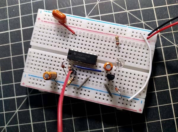
A cupboard light is a small and useful undercabinet light source that can be easily installed in cupboards, wardrobes, and kitchen cabinets. It can shed light into dark corners and the tiniest nooks and crannies within them. In this post you will see the design idea of a little cupboard light that can illuminate even the darkest corner well to find whatever you are looking for in a jiffy.
Well, let us first look at its circuit diagram…
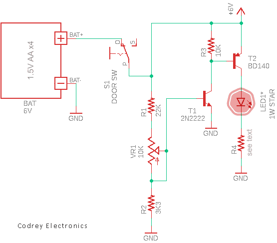
Now let us see the list of required components…
- BAT: 6V Battery (1.5V AA x4)
- S1: Wardrobe Light Switch (push-to-break)
- R1: 22KΩ ¼ W Resistor
- R2: 3.3KΩ ¼ W Resistor
- R3: 10KΩ ¼ W Resistor
- R4: 7.5Ω 2W Resistor
- VR1: 10KΩ Potentiometer
- T1: 2N2222 NPN Transistor
- T2: BD140 PNP Transistor
- LED1: 1W Star White LED
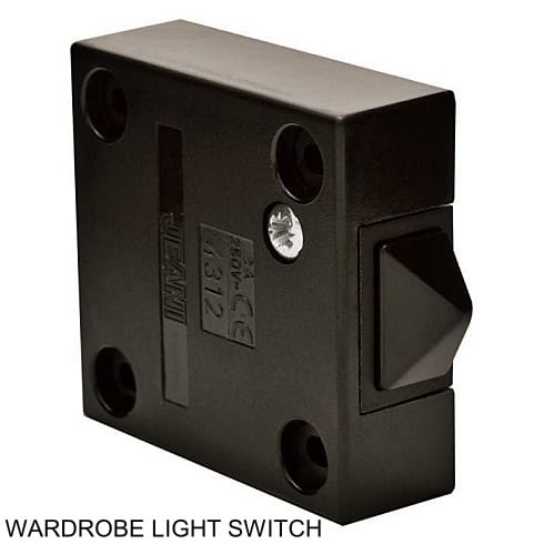
As you can see in the schematic above, the light source in this 6V battery powered cupboard light system is a 1W star white LED (LED1). The push-to-break type door switch (S1) is to turn on the system only when the cupboard is opened. Potentiometer (VR1) allows you to control the intensity of the light source from zero to almost full brightness and vice versa.
Below table shows the typical electrical characteristics of the 1W star white LED that comes with an aluminum PCB.

The power LED star offers an extremely high light output in an energy efficient way and it comes mounted on to special PCB star that acts to draw heat away from the LED, therefore extending its operational life.
Note at this point that the value (and power rating) of the current limit resistor (R4) pointed here has been calculated for the aforementioned 1W star white LED. So, if you make any modifications to the light source, you must ensure that you employ a suitably rated current limit resistor of the correct value.
As an aside, typically wood colour cabinetry looks good with warm white LEDs and white cabinetry looks great with cool white LEDs.
The LED dimming trick implemented here offers some advantages, such as attractive simplicity. Despite some shortcomings, the concept fits well with this little application.
It is something you know LEDs can basically be dimmed in two ways – analog and pulse width modulation dimming.
Analog dimming changes the light output by simply adjusting the DC current through the LED, while pulse width modulation dimming achieves the same effect by varying the duty cycle of a constant current to effectively change the average current through the LED.
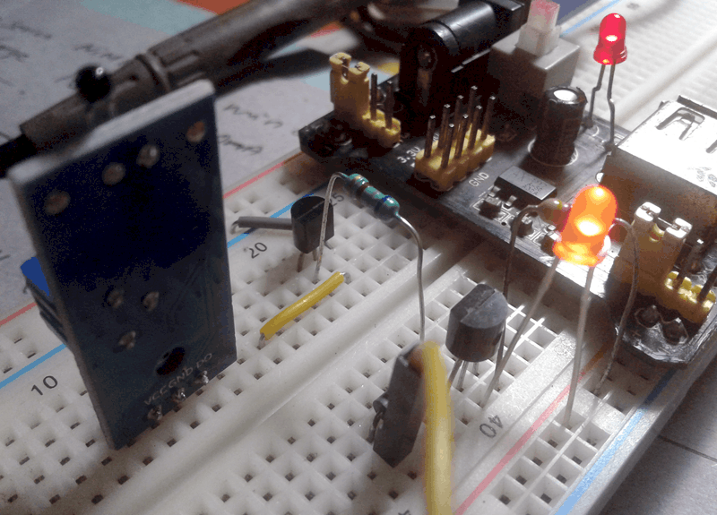
As usual, first I built the circuit on a mini breadboard for some quick tests.
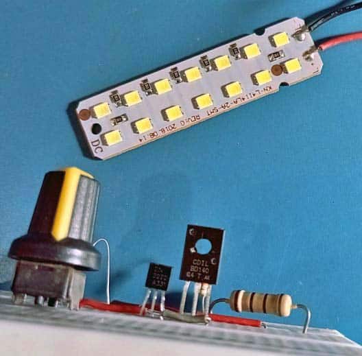
Also, it was tested with a casually picked 3.7V-4V white LED panel. It worked as expected.
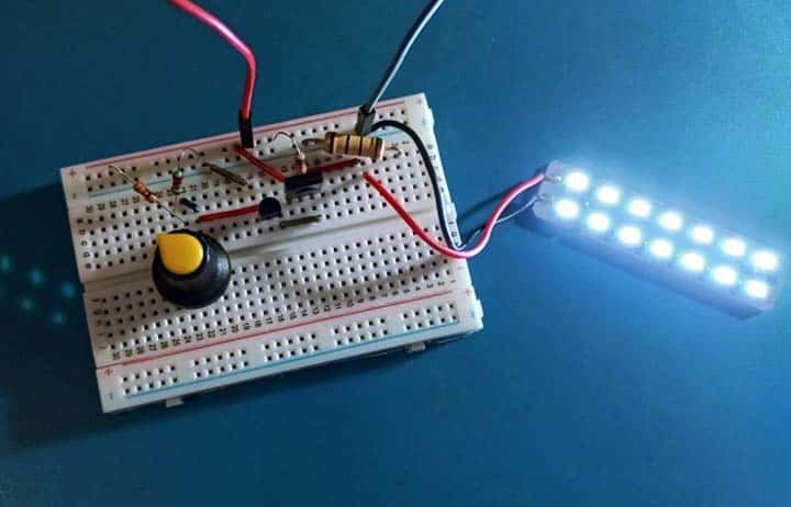
That is all for now. Hopefully you all found this post interesting and useful. Feel free to ask questions if you care to. I will remain available. Have Fun!

