I recently received a request to share some simplest ideas for converting regular cone markers to lighted cone markers. So, this post explains an idea to make your own lighted cone markers using a handful of cheap electronics parts. Well, let us get started…
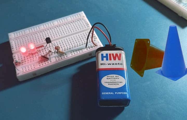
First look, these are the plastic cone markers I bought from Amazon to start the project (the final construction is not done yet).
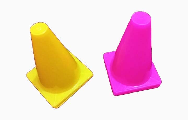
Cone markers are commonly used to mark an area. The circuit below allows you to make an illuminated cone marker with a day/night auto-detection mechanism.
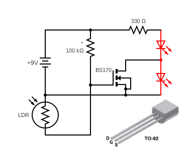
The main component in this little circuit is the N-channel enhancement mode field effect transistor BS170 (a small signal mosfet). Next is a regular photoresistor (LDR). The circuit is set up in such a way that two LEDs light up during the day and only one LED lights up at night. The 100KΩ is a test-selected resistor, and the 330Ω is the LED current set resistor.
Ultra-Red (or amber) 10mm LEDs are recommended for this project. A 9V battery can be used as the power source.
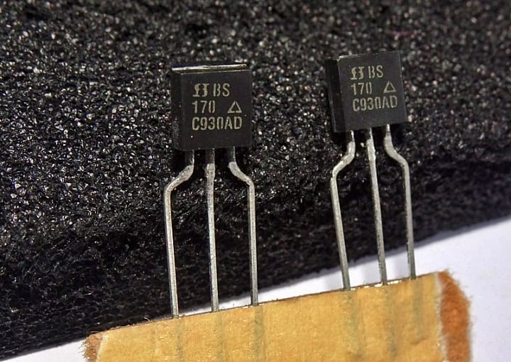
As an aside, always try to buy BS170 MOSFETs from reputable sources because Chinese cheats may have labeled the 2N7000 MOSFET as BS170 MOSFET. The 2N7000 MOSFET has a lower current rating, and its Drain and Source pins are transposed.
I generally post things as I do them even if they are not utterly complete. Below you can see my breadboard version of the circuitry (just a proof of concept).
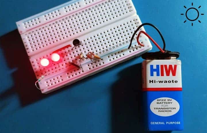
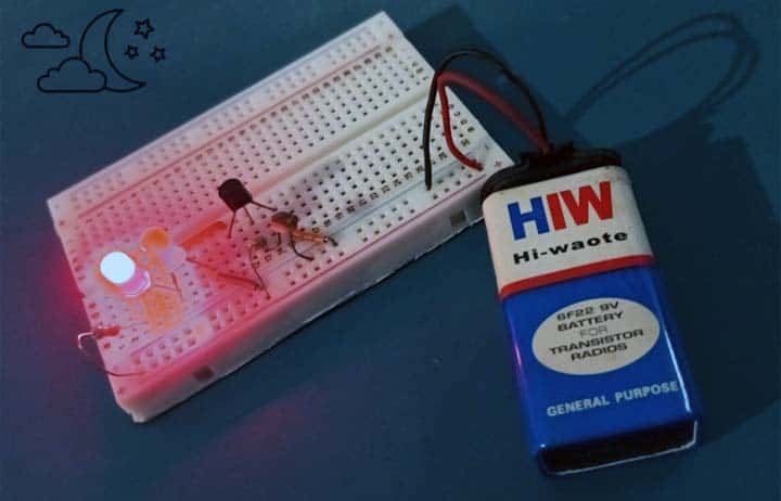
Keep note that this design is completely optimized for the application and all the part values interact, so any variation on the design means you pretty much have to tweak all the values up yourself (the basic scheme is very simple but has few drawbacks).
That is all for now. The goal of this post is to provide a simple design example. An in-depth understanding of the theory should not be required to reconstruct the design example on your own. Spotted a mistake? Enjoying this project? Any opinions on forthcoming articles and projects? Let me know!

