A programmable gain amplifier (PGA) is an electronic amplifier, typically based on an operational amplifier (op amp), whose gain can be changed by external control signals.
Recently, I have been thinking about a basic programmable gain amplifier that can be quickly set up with minimal electronic components, with the idea of sharing experimental circuits that can be easily handled by most of the readers.
So, here is the design idea for a distinctive programmable gain amplifier. Its operation is straightforward and intuitive.
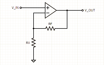
This is in fact a textbook non-inverting programmable gain amplifier design. Those who recall the op amp theory, just note that gain of this non-inverting amplifier is set by the ratio (RF/RX)+1
To ‘program’ the gain, we can change out the value of RX by switching some resistors in and out through some analog switches as pointed in the below figure.
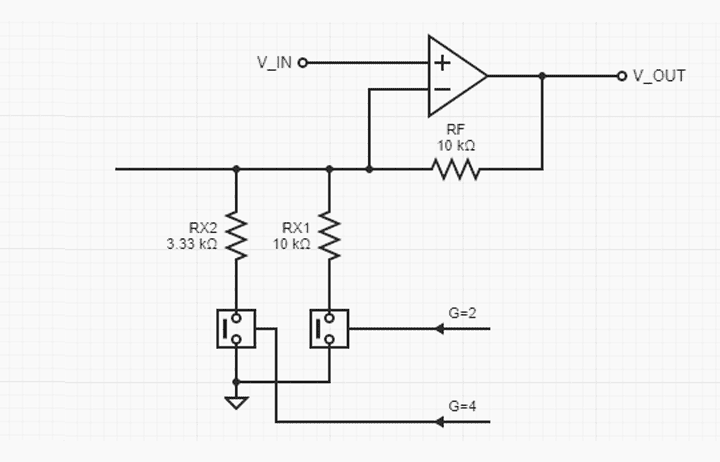
So, the amplifier’s gain can be varied handily via a bunch of resistors and analog switches. Toggling the analog switches one at a time (perhaps thru logic bits) swaps the resistors in the op amp’s feedback network effectively changing the gain.
Keep note at this point that most silicon switches have an on-resistance (RON) in the range of circa 50Ω-500Ω which limits the gain accuracy to some extent. Therefore, the gain formula should be modified as G = (RF/RX+RON)+1
As you might expect, there are several ways for potential betterments – we will get in to that after a while. It is time to look at another version of the canonical programmable gain amplifier design idea.
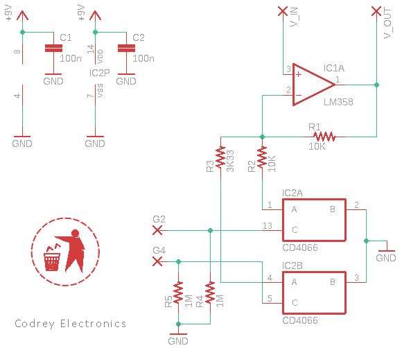
As you can see, a 4066 bilateral switch IC is employed here to digitally switch the feedback network resistors. The CMOS chip contains four analog switches which can be controlled by a digital signal (H=ON/L=OFF).
For the bilateral switch it does not matter in which direction the analog signal is applied, but according to TI datasheet, the closed switch has a typical on-resistance fairly close to 470Ω at 5V VDD (TA=25°C) and 180Ω when VDD=10V.
Sadly, the on-resistance varies from device to device. It varies with temperature and voltage level as well. So, if overall accuracy is essential, then consider the following alternatives:
- Small Signal Relays/Reed Relays
- Low on-resistance (RDSON) Mosfets
- Low Ohmic resistance (RON) SPST switch ICs such as ADG412
The alternative setup shown below wipes out the drawbacks of the on-resistance problem.
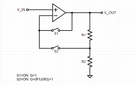
Like in the previous configuration, we can change the gain by individually closing the gain selector switches.
However, a closer look shows that on-resistance is not in series with the gain selector resistors. But a slight offset error occurs due to the bias current flowing through the switch.
Moreover, the switch’s on-resistance and capacitance to ground at the input of the op amp, create a low-pass filter (LPF) in the feedback loop that may thrust the response towards ringing or oscillation. Therefore, you might need a small (pF) capacitor across R1 to keep it stable.
Jumping to a quick conclusion, a programmable gain amplifier, in concept, is an op amp-based noninverting amplifier with user-programmable gain. It is usually used in analog signal processing schemes where an input signal has deficient amplitude. It can also be used as a unity gain amplifier to buffer the inputs of lower impedance segments.
Needless to say, you can simply use a regular potentiometer in a programmable gain amplifier design for manual gain adjustments. But if you need gain adjustments by way of digital control it might not be a walk in the park. As with any design there are unseen problems to watch out for!
You can also make your own PGA using a digital potentiometer (with SPI or I2C interface) and an op amp. As a proven example, the venerable MCP41010 digital potentiometer lets you to insert a digitally controlled resistance into a PGA circuit.
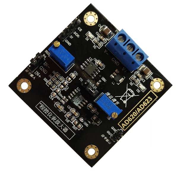
Finally note that readymade Chinese modules with the MCP41010 and AD620/623 Integrated Circuits (ICs) are also still available from several sources (see below). Those looking for crosscuts can try such generic modules without much effort.
Well, stay tuned for further thoughts on this complex topic. Thanks for reading!

