This post is about the far-famed and widely-used 741 classic operational amplifiers!
While not attempting to share numerous potential applications, it includes one basic circuit idea that can be tweaked well to applications other than what is demoed. Well, let us get started…
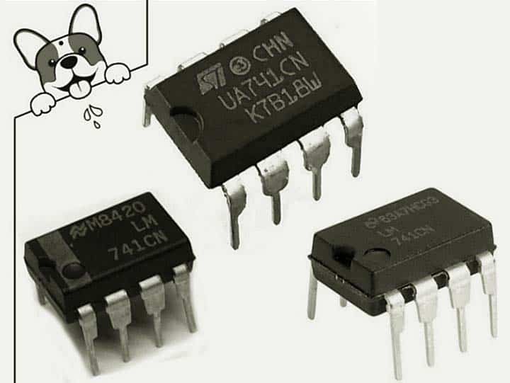
What exactly is an operational amplifier (op-amp)?
Simply, an op-amp is a two-input device that can perform mathematical operations upon their inputs.
The schematic symbol for an op-amp (see below) has two inputs – the non-inverting input (+) and the inverting input (–), as well as one output. The op-amp takes the signal from the non-inverting input, subtracts the signal from the inverting input, multiplies the result by a large factor called the gain, and then outputs the result as a voltage.

Now note that an op-amp uses external feedback to control its functions, and a real op-amp IC has additional pins for power supply connections and sometimes for further external adjustments as well.
If you have learned analog electronics, operational amplifiers will be familiar to you because op-amp is a key component in analog circuits. The most popular op-amp IC of all time is the uA741 designed by Dave Fullagar (https://www.computerhistory.org/collections/catalog/102739975) while working for Fairchild in 1967.
You may notice, while today’s op-amp chips have superb features (that is something for another post), the 741 IC remains widely beloved and in active production today, over around 50 years later!
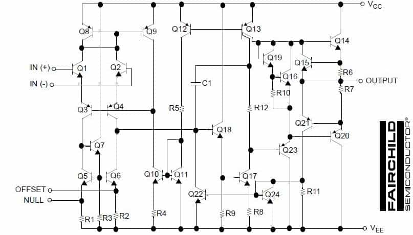
And, here is its schematic diagram. Since the internal electronics of the 741 op-amp has been explored in respective articles, just recall at this point that the main functional blocks of the 741 op-amp IC are a differential amplifier, a bias generator, a gain stage, and an output stage.
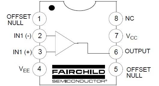
A few more little bits to consider:
- All input signals at the IN(-) pin will be inverted at the OUTPUT pin
- All input signals at the IN(+) pin will be processed normally i.e. without inversion
- The VEE pin is the negative supply voltage terminal
- The VCC pin is the positive supply voltage terminal
- OFFSET NULL pin is to eliminate the offset voltage and balance the input voltages (since the op-amp is the differential type, input offset voltage must be controlled so as to minimize offset).
- Offset voltage is nulled by application of a voltage of opposite polarity to the offset, and an offset null-adjustment potentiometer may be employed to compensate for offset voltage.
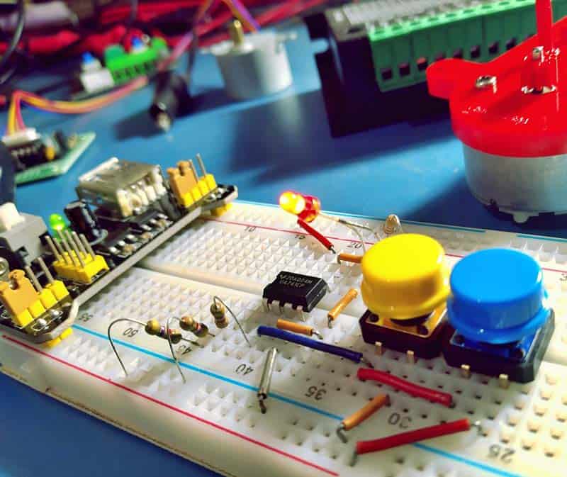
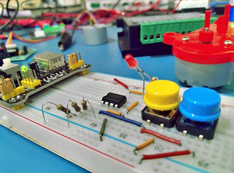
Learning how to build, test, and run circuits is a useful skill, it does take a little practice though. So if you are envisioning doing some practical projects based on the 741 op-amp IC, you can start from here. Effectively, this is a crude bistable switch circuit centered on the commonly available UA741CP.
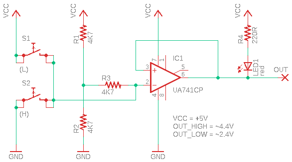
The circuit really is that simple, and on the test bench, proved versatile. The circuit operates as follows.
As you can see in the well-annotated schematic above, non-inverting input (pin 3) of IC1 is directly wired to the output (Pin 6). And, the inverting input (Pin 2) is biased to ½ Vcc via R3 and the R1-R2 potential divider.
Normally, S1 and S2 are open. If S1 is briefly closed, the inverting input is momentarily pulled High and the output goes to Low and remains in that state until S2 is closed. When S2 is briefly closed, the output goes High and stays in that state until S1 is again operated.
Note here that the output (OUT) can happily drive a low-current LED as an indicator of output (LED1 in the schematic). The same pin can also handle large loads such as a buzzer, lamp, or relay, provided there is an appropriate power driver circuit between them.
Finally note that some op-amp ICs work fine as comparators within their limits and the 741 is one of these. And, do not forget to go through this great writeup of 741 op-amp IC (https://en.wikipedia.org/w/index.php?title=Operational_amplifier).

Nice article.
To start with – where would one use it, common applications, or general use cases is what I was interested in.
Shashi Kiran: You can start with the practical example project shown here. Also, I am listening to your suggestions to improve future posts. Thanks!